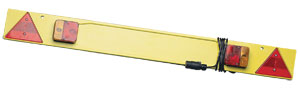
When carrying cycles with a cycle carrier (or any other load which obscures the vehicle's lights and/or registration plate) a suitable lighting board and approved number plate must be fitted to the load. Obscured lights or number plates can incur a fine and penalty points added to the driver's licence
Obscuring means any object placed in the normal field of view of the lights and number plate. This includes cycle wheels, regardless of whether the lights can be seen through the spokes of the wheel.
Fitting a lighting board to a towbar-mounted cycle rack is straightforward as the towbar will also feature an electrics socket into which the lighting board is plugged into. The lighting board is then securely attached to the rack or the cycles by means of a strap, and you are ready to drive away - legally.
When using a strap-on cycle carrier on a standard car however, no such provision exists to power a lighting board - indeed it is usually users of a strap-on rack that are most commonly prosecuted. Lack of a facility to power a lighting board does not remove the obligation to use one whenever carrying cycles on the rear. However it is fairly straightforward - and cheap - to install a socket for your lighting board, without fitting a complete towbar to the vehicle.
FITTING A 7-PIN SOCKET FOR A LIGHTING BOARD.
Parts Required (See bottom of page for links)
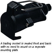
- 7-pin N-Type Trailing Socket
- 7-core cable (1 metre approx.)
- Audible Monitor Relay or 7-way Bypass Relay*
- 9 electrical snap connectors (or your preferred electrical connection)
- 1 Ring terminal
- Cable Ties
- PVC Tape
*If your car has a multiplexed or CAN-bus wiring system on the vehicle lighting circuits, a full smart bypass relay containing an integral audible buzzer must be fitted to protect the electrical systems. Also see How to fit a Bypass Relay in conjunction with this article for vehicles with multiplexed/CAN-Bus wiring
INSTALLATION.
Overview:
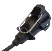
Rather than mounting the electric socket outside the car under the bumper as is the norm for a towbar, the socket is usually mounted inside the boot. A trailing socket is the most common installation as it is the least invasive and can often be coiled up neatly inside a luggage/first aid boot compartment if one exists. It is possible to mount a standard towbar socket to the interior trim but this means making holes in the trim to mount the socket and to feed the cable through. Which socket you use is a matter of user preference, but should be mounted somewhere where it is safe from accidental damage from loading etc.
When in use, the cable of the lighting board is fed through the boot lid into the boot and plugged together inside the car. Most vehicle's door seals are flexible enough to allow the cable to pass through and the boot to be closed without damaging the cable, which is the method used in this guide. In rare circumstances where this is not possible, an alternative mounting arrangement must be fabricated outside the vehicle - behind or below the rear bumper, and the cable fed into the vehicle through either a convenient grommet or by drilling a hole and sealing the hole with a grommet. This will often require a longer length of 7-core cable.
Assembling the socket & cable:
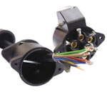
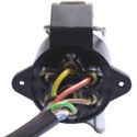
Open the N-type socket and loosen the grub screws on each of the 7 pins and also the cable securing strap. Pass first the cable through the socket's rubber grommet then through the socket body. Remove about 1 inch of the outer insulation of the cable, then strip each of the 7 wires by about 3-4mm.
Insert each wire into the 7 pins as per the diagram (viewed from the connecting side of the socket) and tighten the grub screws.
Tighten the cable securing strap to prevent the wires being pulled from the pins, close the cover of the socket. Tighten the cover screws and finally the knurled plastic nut securing the rubber grommet over the cable exit hole.
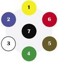 |
Pin 1 |
Yellow |
 |
|
Pin 2 |
Blue |
||
|
Pin 3 |
White |
||
|
Pin 4 |
Green |
||
|
Pin 5 |
Brown |
||
|
Pin 6 |
Red |
||
|
Pin 7 |
Black |
Connecting to the vehicle:
Identify which side of the vehicle the wiring loom runs. Install the socket on that side of the vehicle wherever possible. Note that on some vehicles the loom splits at the front of the vehicle and runs to the rear lights down each side of the vehicle. In this case, establish which side of the vehicle has the foglight wiring (usually the offside, but on vehicles with foglights in the tailgate the wire may be on the nearside) and installation may require an extra length of twin-core cable to connect to the functions on the opposing side to the installation.
(For Multiplexed or CAN-Bus systems using a bypass relay see additional guide on fitting a full bypass relay)
Strip about 3 inches of the outer insulation from the 7-core cable. Do not strip the individual wires. (This guide uses snap-connectors for installation. If using alternative connections, stripping the wires may be necessary depending on the style of connector)
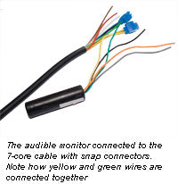
Firstly, connect the audible monitor relay:
Take the yellow and green wires on the relay and connect each to their matching coloured wire on the 7-core cable with snap connectors. To prevent "pulling apart" of the connection, it is advisable to inset both wires into the snap connector from the same direction.
Now, connect to the vehicle:
From the audible monitor:
Connect the orange wire to the vehicle's left indicator.
Connect the grey wire to the vehicle's right indicator.
From the remaining wires on the 7-core cable:
Connect the blue wire to the vehicle's foglight.
Connect the brown wire to the vehicle's offside tail light.
Connect the red wire to one of the vehicle's stop lights.
Connect the black wire to the vehicle's nearside tail light.
Finally earth the installation to bare metal on the vehicle bodywork:
Using a ring terminal on the white wire from the 7-core cable, and the remaining wire (black or white depending on the brand of relay) from the audible monitor relay, connect these wires to a suitable earth point on the metal bodywork. Some vehicles have a convenient existing earth terminal near the light cluster, otherwise use a bolt or self-tapping screw to bared metal for a good connection.
To establish which wire corresponds to each function, it is useful to have an assistant sat in the driving seat, operating each function in turn. Use a simple test light with bulb and a test probe at the wires entering the rear light clusters to find the live wire when a particular lighting function is switched on. Double check by having your assistant turn the function off - the test lamp should also go off. (Note for multiplexed / CAN-Bus vehicles an LED test lamp or digital multimeter should be used, and the vehicle lights must remain connected during installation)
CHECKING THE INSTALLATION.
Plug your lighting board into the trailing socket and position where it can be seen from the driver's door. Turn on each function in turn and verify that the lighting board displays correctly. To check that the earth connection is sound, be sure to check the board with tail lights, stop lights and indicators on simultaneously. When indicators are on, the light from the stop and tail lamps should be bright and constant, and not fluctuate noticably as the indicators flash. Severe dimming with numerous functions on is a sure sign of a bad earth connection on the white wire from pin 3 of the socket to the earthing point on the bodywork.
When the indicators are operated, the audible monitor relay should sound in time with the indicators. This allows the driver to confirm that the indicators are functioning correctly, in the same way as the dash mounted light confirms operation of the car's indicators. If no sound is heard from the monitor during testing when either indicator is operated, the installation of the monitor is probably at fault. Check that the yellow and green wires from the 7-core cable are connected ONLY to the yellow and green wires from the monitor. The only wires connecting to the vehicle's indicator wires should be the orange and the grey wires from the monitor.
In use, if the indicators are operated and no buzz is heard, this indicates either a fault on the lighting board or an incorrectly connected or disconnected plug.
FINALISING THE INSTALLATION.
Once installation is successfully completed and checked, wrap any connections in PVC tape. The buzzer should be secured to the loom with tape or cable ties. To prevent pulling the connections whilst using your new lighting socket, use a cable tie to secure the 7-core cable to the loom or bodywork.
Coil the cable away in a convenient place where it will be safe from damage from loading. The metal loop of the inline socket can be used to hang the socket from if a convenient hanging location exists.