For both people undertaking fitting a towbar for the first time, and those who have fitted a towbar previously and are considering fitting a towbar to a modern car, the prospect of wiring the towing electrics may seem daunting at first.
Many modern vehicles cut down on weight, size and volume of the wiring looms by using electronic control systems to operate the vehicle's lights. You may hear these systems referred to as "multiplexed" or "CAN-Bus" systems, which all sounds quite complicated. In some ways the systems are complex, but it is not necessary to have a complete understanding of these systems in order to fit towing electrics. This guide does not set out to give such a complete understanding, rather to give a general idea of the nature of the systems - it should not be viewed as an electronics textbook, indeed the vaguaries of the guide may seem incorrect to the expert - however the expert is not who this guide is aimed at.
So what are "multiplexed" and "CAN-Bus" systems?
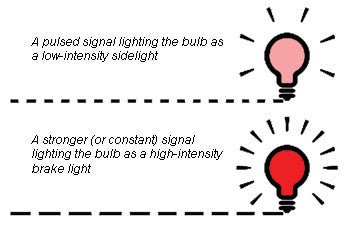
The term CAN-Bus refers to a Controlled Area Network which, to the DIY towbar fitter means absolutely nothing. It is easier to visualise using the term "multiplex". Essentially, these systems carry low-current and sometimes low voltage signals from the lighting controls down to the lights, which "tell" the vehicle lights what to do. The signal wires may also carry varying signals, for instance in the case of a single brake/tail light bulb, it's single signal wire can carry 2 signals - one instructing the bulb to light at low intensity, the other when the brakes are operated to light the bulb at high intensity. These signals when examined with a simple circuit tester with a filament bulb appear to be constant signals, however they may be rapid pulses of electrical current, which are faster in frequency than the time a bulb takes to illuminate - and may be faster than discernable with the human eye, so the signal appears constant.
This causes the fitter a problem in that the trailer or caravan lighting is traditional filament lighting with one wire per function and is not designed with these "multiplexed" systems in mind. What is needed is a way of "translating" the vehicle's pulsed shared signals into constant 12 volt supplies to each light on the trailer or caravan.
The 7-way smart bypass relay does the job of translating these signals and is a simple in-line fit between the towbar wiring and the vehicle loom. The fitter need not have an in depth understanding of the "multiplexed" system - the smart bypass relay's inbuilt microchip does all that. Fitting is very straightforward.
How the relay works
A relay sounds complex but essentially it is simply an electrically operated switch. Imagine a push-button switch. When your finger pushed the switch, power is allowed through the switch (ON). When your finger is removed, power is blocked through the switch (OFF). Now visualise that switch but replacing your finger for an electrical wire. When power is sent down the wire, this "pushes" the switch, turning the relay on. When the power down the "finger" wire is removed, the relay switch is turned off. The 7-way bypass is a miniature bank of 7 of these electrically operated switches. When fitted it has a main 12 volt power supply into the 7-way unit, and 7 output wires leading to the towbar's electric socket. Also into the relay are 7 "switching" wires which connect to the vehicle's lighting circuits. When for instance the brake is operated, a tiny current from the vehicle's brake light comes into the relay and switches the towbar's brake light circuit on. Power is then allowed through from the main 12 volt relay supply wire, and out of the relay to the towbar electric socket's brake light wire. When the brake lights on the car go off, there is no current into the relay's brake light switching wire, so the power to the trailer brake light is switched off.
Fitting the bypass relay.
The traditional way of wiring in a towbar's electrics was to take each of the lighting wires to its corresponding wire on the car (i.e. Blue for foglight to foglight wire on car, Brown for right tail light to right tail light on car and so on). Since the vehicle's signal wires are incompatible and of too low a current rating to supply each light in this way, the bypass relay is simply fitted in between. The principle of connecting remains almost the same.
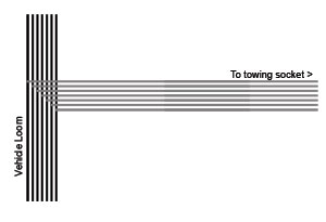
A simple direct connection installation to a non-"multiplexed" vehicle
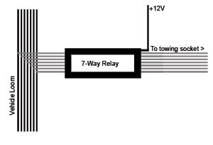
Installation using a bypass relay is not far removed from the direct connection method. The relay is simply positioned between the socket and the point of connection to the vehicle
Step-By-Step Installation
1) Firstly feed the 7 core cables from the towbar sockets into the vehicle, making sure the cable is kept well away from the vehicle exhaust and at the side where the main vehicle loom runs (Note that some vehicles have a loom which splits into left and right at the front of the car and is fed down both sides - in which case choose the side where the foglight -and reverse when fitting a grey supplementary socket- wiring is located. On these "split loom" systems it will be necessary to extend some of the wires to make the connections to the functions on the opposite side of the vehicle where the towbar wiring is installed.)
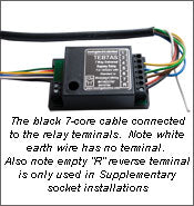
Strip the outer insulation of the 7-core cable/s by approximately 3 inches - then strip 3-4mm from the insulation of each individual wire. Take the smart bypass relay, and insert each of the following wires from the BLACK 7-core cable into the screw terminals of the relay, and tighten the screw. Ensure that no stray strands of wire are protruding from the terminals and also that there is no un-insulated bare wire visible once the connection has been made.
Relay Terminal |
Insert wire colour |
|
1 (L/H Indicator) |
Yellow |
|
2 (Foglight) |
Blue |
|
4 (R/H Indicator) |
Green |
|
5 (R/H Tail) |
Brown |
|
6 (Stop Lights) |
Red |
|
7 (L/H Tail) |
Black |
|
8/R (Reverse) |
Yellow from Grey 7-Core* |
|
* Only where Grey supplementary socket is fitted. |
|
TT Terminal:
Some variants of the relay have a terminal marked "TT". This allows a dash-mounted warning light to be fitted instead of the built-in buzzer as an option. Normally this is not used and is NOT an earth terminal!
2) You will notice that there are 8 (9 on some relays depending on manufacturer) wires coming out from the relay which apart from the grey wires, match the colours of the wires in the black 7-core cable. These colours are the standard colours for towbar wiring - unfortunately there is no such standard for vehicle lighting wiring colours.
An assistant sitting in the driving seat is useful at this stage as we begin to identify the vehicle's wiring. You will also need a notepad and pen.
Make sure that if the vehicle lights have been removed or disconnected whilst fitting the towbar; they are re-connected and functioning correctly, replacing any blown bulbs if any are noted before proceeding - faulty lights will lead to a faulty towbar installation.
- Switch on the vehicle's left indicator and test the wires leading to the left hand wiring loom with your circuit tester. The wire on which your tester visibly flashes in time with the indicator light will be the feed wire for the indicator. Make a note of which wire this is (i.e. L/H indicator = Blue).
- Now switch on the vehicle's side lights. Test the wires again at the left side and find the wire showing a positive voltage. Now turn the side lights off. If that wire is now showing no voltage, this will be the feed for the left hand sidelight. Now operate the brake lights. If this sidelight wire again shows a positive voltage higher than that for the side light (or the LED lights brighter) then this is a shared feed for both the brake and the side lights. Make a note of this.
- Identify the right hand indicator in the same way as for the left and again make a note.
- If the sidelight feed is not a shared feed with the brake lights, identify the right hand sidelight.
- If the sidelight feed is not a shared feed with the brake lights, operate the brakes and identify the brake light wire - this only needs doing for one side of the vehicle.
- Operate the foglight and identify the feed.
- If a grey supplementary socket is fitted, identify the reversing light feed.
3) You are now ready to begin connecting the relay signal wires to the wires identified according to the following table
Relay Wire |
Connect to: (on vehicle) |
|
Yellow |
Left Indicator |
|
Blue |
Foglight |
|
Green |
Right Indicator |
|
Brown |
Right Tail Light |
|
Red |
Stop Light |
|
Black |
Left Tail Light |
|
Grey* |
Reverse Light* |
|
* Only where Grey supplementary socket is fitted. On some variants of the relay there may be two grey wires - in this case connect one of the grey wires (either - it is not important which) to reverse. The other grey wire goes to Earth on the vehicle body |
|
Important!
Thin wires twisted tightly together signify CAN-Bus control wires. These wires should not be connected to or otherwise interfered with - not even with a circuit tester.
4) The relay does not use the car's lighting circuits to power the trailer lights, only to switch them. Power comes from an independent power supply into the relay. From the battery's +ve terminal - or from a main 12v power supply to the fusebox or a power distribution rail (often under the dashboard), connect a wire of minimum current rating 21Amps to the relay's screw terminal marked 12v or +12V I/P(input). This is the power supply wire for the trailer lighting and should be fused at 15Amps (a maximum of 20Amps - see the instructions accompanying the relay). Install the fuseholder as close to the battery (or fusebox power take-off point) as possible. Do not insert the fuse yet.
5) To a suitable earth point on the metal vehicle body take the following wires: White from Black 7-core cable. White from Bypass relay. Both white and black wires from the Grey 7-core cable (if grey supplementary socket is fitted). For bypass relays with two grey wires, also earth the remaining grey wire. Use ring terminals to make a sound electrical earth connection - look for an existing earthing point and use that if one already exists otherwise it may be necessary to drill a small hole, bare the metalwork and use a small bolt or self-tapping screw to make the earth connection.
6) Make a final check of all your connections
7) Insert the fuse for the relay's power supply wire, plug your trailer, caravan or lighting board into the socket/s and check that all road lights are functioning correctly.
Troubleshooting:
| Problem | Solution |
| Vehicle has only one wire feeding both the brake and side lights | Disregard both the brown and black wires from the relay and connect only the red wire to this shared wire on the loom. The relay will operate the side and brake lights from this single signal. Tape up the brown and black wires. |
| The vehicle has only one wire feeding both the side lights and fog lights | As above, disregard both the brown and black wires from the relay and connect only the blue wire to this shared wire on the loom. The relay will operate the side and fog lights from this single signal. Tape up the brown and black wires. |
| Buzzer sounds continuously | TT terminal connected to earth. Disconnect |
| Relay "Sticks" leaving one light permanently on |
Mixed signals to relay during installation and testing. Remove power supply fuse for a few minutes, then replace, to reset the relay |
| Relay appears not to function | a) Installer error. Re-check all connections b) Car battery low - Run engine to charge battery then re-test c) (New unregistered vehicles) Check that full pre-sale CPU download has been completed. |
| (Rover 75) Relay initially appears to fail on fitting | After completing the installation, reset the vehicle's checking system by turning every road light (including fog/reverse) on and off. |
| (Vauxhall Vectra) 10/15 second regular "tick" when vehicle off and number plate courtesy light still on | Normal reaction to car's checking system. No fault. Tick stops when courtesy light extinguishes. |